- +86-755-23012705
- Building 3, Jinfeng Industrial Park, Fuyong Street, Baoan District, Shenzhen ,China
- [email protected]
Menu
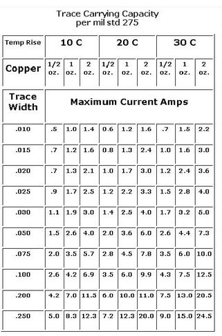
 We generally have a common sense when drawing PCBS, that is to use thick lines for high current (such as 50mil or above), and thin lines for low current (such as 10mil).
For some electromechanical control systems, sometimes the instantaneous current flowing through the wire can reach more than 100A, so the thinner wire is bound to cause problems.
A basic rule of thumb is 10A/ square mm, which means that a wire with a cross-sectional area of 1 square mm has a safe current of 10A. If the width of the line is too thin, it will burn out when large current passes through it. Of course, the current burn out wire should also follow the energy formula: Q=I*I*t. For example, for a wire with 10A current, a 100A current burr suddenly appears with a duration of US class, then the 30mil wire is definitely able to withstand. Another problem is the stray inductance of the wire. This burr will produce a strong reverse Electromotive force under the action of the inductor, which may damage other devices. The thinner and longer the stray inductance of the wire is, the larger the stray inductance, so the length of the wire should be considered in practice.) General PCB drawing software usually has several options when laying copper on the through-hole welding plate of the pin of the device: right-angle spokes, 45-degree spokes and straight spokes. What’s the difference? Novice often do not care too much, choose a random, beautiful on the line.
Not really. There are two main considerations:
One is to consider not to heat too fast, two is to consider the current capacity. The use of a straight shop is characterized by a strong overcurrent capacity of the solder plate, which must be used for high-power circuit device pins. At the same time, its thermal conductivity is also very strong, although it is good for device heat dissipation, but it is a difficult problem for circuit board welding personnel, because the heat dissipation of the welding plate is too fast to hang tin, often need to use more watts of soldering iron and higher welding temperature, reducing the production efficiency. Using right-angled spokes and 45-angle spokes reduces the contact area between the pin and the copper foil, allowing slow heat dissipation and making welding easier.
Therefore, the choice of brazing through the hole pad connection mode to be considered according to the application, combined with the overcurrent capacity and heat dissipation capacity, low power signal line does not use straight shop, but through the large current pad must be straight shop. As for a right Angle or a 45-degree Angle, it looks beautiful.
Why bring this up? I have been studying a motor driver for a while. The H bridge component in this driver keeps burning down, and I can’t find the reason for it for four or five years. After a lot of hard work, I finally found out that the welding disk of a device in the power loop used right-angled spokes in laying the copper (and due to the poor drawing of laying the copper, only two spokes actually appeared). This reduces the overcurrent capacity of the entire power circuit.
Although the product does not have any problems during normal use, it works completely normally under the condition of 10A current. However, when there is a short circuit in H bridge, a current of about 100A will appear in the circuit, and the two spokes will burn out immediately (US class). Then, power circuit into a circuit, energy storage on the motor without discharge channel is distributed through every possible way, this energy will be consumed flow resistance and related operational device, to destroy the bridge road control chip, and signal into the digital circuit of the power supply, causing severe damage of the entire device. The whole process was as thrilling as detonating a large landmine with a single strand of hair.
So why, you may ask, are only two spokes used on the solder pad in the power loop? Why not let the copper foil go straight through?
Because, the people in the production department said that the pin was too hard to weld! The designer listened to the production people and that’s why…
Alas, discover this problem can really expend my brain one-time, which elephant say so simple, bitter joy from oneself know! If the hole of VIA is less than 0.3mm, there is no way to use mechanical drilling. If laser drilling is to be used, it will be more difficult to produce and process the plate. So, my personal opinion is that if it is not very necessary, the minimum is 0.5mm outside /0.3mm inside. But things like computer motherboards, memory chips, dense BGA packages, etc., can sometimes be as small as 14mil/8mil.
My personal idea is that the diameter of the hole is generally 1.5 times the width of the line, but of course special bold lines (such as power supply, etc.) do not need this.


XPCB Limited is a premium PCB & PCBA manufacturer based in China.
We specialize in multilayer flexible circuits, rigid-flex PCB, HDI PCB, and Rogers PCB.
Quick-turn PCB prototyping is our specialty. Demanding project is our advantage.
Tel : +86-136-3163-3671
Fax : +86-755-2301 2705
Email : [email protected]
© 2023 - XPCB Limited All Right Reserve
