- +86-755-23012705
- Building 3, Jinfeng Industrial Park, Fuyong Street, Baoan District, Shenzhen ,China
- [email protected]
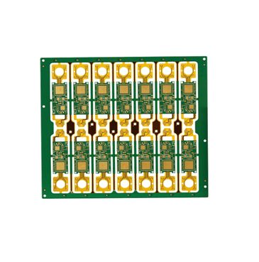
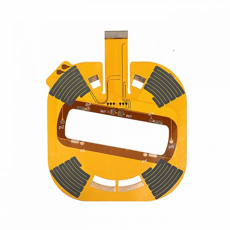
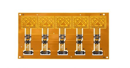
Rigid-flex printed circuit boards (PCBs) are a hybrid of both rigid and flexible boards, combining the benefits of rigidity for structural support and flexibility for space-saving and dynamic movement. They have become increasingly popular in industries such as aerospace, automotive, medical devices, and consumer electronics due to their unique advantages. However, the soldering process for rigid-flex PCBs presents specific challenges that require careful attention and tailored solutions. In this blog, we will explore these challenges and provide insights into the solutions that ensure successful soldering and overall PCB reliability.
Rigid-flex PCBs typically feature a combination of rigid and flexible layers, with copper traces, solder masks, and vias integrated across both sections. The construction often includes several layers—rigid layers on one side, flexible layers on the other, and sometimes additional interlayer connections (via-in-pad, blind vias, etc.).
Challenge: The multilayer design makes the soldering process more complex, especially when dealing with both rigid and flexible sections simultaneously. The different materials in the rigid and flexible areas—such as FR4 for the rigid sections and polyimide for the flexible sections—have different thermal expansion rates, which can lead to stress on the solder joints during heating and cooling cycles.
Solution: Careful temperature management is crucial in the soldering process. Using a temperature-controlled reflow soldering system allows for a precise ramp-up and ramp-down of temperature to avoid thermal mismatch. Additionally, a controlled cooling phase prevents thermal shock and minimizes the risk of cracking or warping the flexible layers.

Rigid-flex PCBs use different materials in the flexible and rigid sections, including polyimide for flexibility and FR4 or other epoxy-based materials for rigidity. These materials have significantly different thermal properties, which can make the soldering process challenging.
Challenge: The difference in the CTE (coefficient of thermal expansion) between rigid and flexible materials can lead to issues like solder joint failure, warping, or even delamination during the heating and cooling phases of soldering. For example, the rigid section of the PCB might expand at a different rate than the flexible section, leading to stresses on the solder joints and possible cracking or void formation.
Solution: To address this challenge, it’s important to choose soldering materials and processes that account for these material differences. For instance, lead-free solder with a higher melting point can be used in combination with a more gradual heating profile. Additionally, selecting materials with better thermal matching properties or incorporating underfill materials between layers can help mitigate the stresses caused by thermal expansion differences.
In rigid-flex PCBs, solder joints are subject to dynamic forces and movements due to the flexible parts of the board. As these PCBs are used in environments where bending or vibration may occur, the solder joints must be able to withstand mechanical stresses without cracking or breaking.
Challenge: The mechanical stress placed on the solder joints in the flexible areas can lead to fatigue and failure over time, especially in applications where the board is frequently bent or moved. Solder joints in these areas are more prone to cracks and can fail prematurely under cyclic loading.
Solution: To improve solder joint reliability, it’s essential to use the correct type of solder, such as lead-free solders with improved ductility. Additionally, selecting a flexible solder mask that can accommodate movement and stress is important. Using reflow soldering techniques that minimize the temperature spikes and mechanical stresses on the joints can also improve the overall reliability of the PCB.
During the assembly of rigid-flex PCBs, the process must accommodate both rigid and flexible sections, each requiring different handling and soldering techniques.
Challenge: Flexible sections of the PCB are more prone to damage and deformation due to their thinness and flexibility. They may also be more challenging to position and secure on automated soldering lines. The need to handle both rigid and flexible areas simultaneously increases the complexity of the assembly process.
Solution: A well-designed fixture that holds the PCB securely during the soldering process is critical. This might involve custom-designed support structures to hold the flexible areas in place without causing damage. Manual soldering, when necessary, should be performed with extra care to avoid mechanical stress on the flexible sections. Additionally, automating the process with specialized equipment that can handle rigid-flex PCBs will ensure greater precision and reduce the chances of defects.

Due to the complexity of rigid-flex PCBs, visual inspection alone may not be sufficient to ensure the quality and reliability of the solder joints. Internal defects such as voids, cracks, or poor solder connections can be difficult to detect without advanced inspection techniques.
Challenge: Traditional methods of inspection, such as visual or X-ray inspection, may not detect defects within the flexible areas, which are more prone to hidden issues due to their nature and construction.
Solution: Advanced inspection techniques, such as automated optical inspection (AOI) for surface-mounted components and X-ray inspection for internal solder joints, are essential for detecting hidden issues. Using high-frequency testing methods like microsectioning or acoustic microscopy can also help in assessing the integrity of solder joints, especially in critical applications like medical devices or aerospace components.

The soldering process for rigid-flex PCBs is indeed more complex than that for traditional rigid or flexible PCBs, but with the right strategies, the challenges can be overcome. Ensuring proper material compatibility, temperature control, solder joint reliability, and precise assembly methods are essential for achieving high-quality solder joints and maximizing the durability of the final product. Advanced inspection techniques and continuous monitoring of the soldering process are also crucial for ensuring the reliability of rigid-flex PCBs in demanding applications.
As the demand for flexible, high-performance electronics continues to grow, mastering the soldering process for rigid-flex PCBs will remain a critical factor in ensuring the success of these innovative technologies.
Your Trusted Partner for PCB Success: XPCB Limited
Let XPCB Limited be your guide to PCB success. Our comprehensive PCB manufacturing, rapid prototyping, and turnkey PCBA services are designed to meet your needs with ease. Count on us to deliver reliable solutions that exceed your expectations. With XPCB Limited, your journey to PCB excellence starts here.


XPCB Limited is a premium PCB & PCBA manufacturer based in China.
We specialize in multilayer flexible circuits, rigid-flex PCB, HDI PCB, and Rogers PCB.
Quick-turn PCB prototyping is our specialty. Demanding project is our advantage.
Tel : +86-136-3163-3671
Fax : +86-755-2301 2705
Email : [email protected]
© 2024 - XPCB Limited All Right Reserve
