- +86-755-23012705
- Building 3, Jinfeng Industrial Park, Fuyong Street, Baoan District, Shenzhen ,China
- [email protected]
Menu

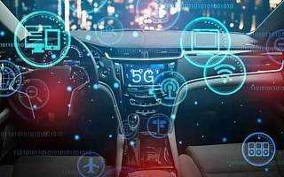
Soon the demand for petrol and diesel will disappear, and if all goes well, so will human drivers. The next time you’re in a Uber, don’t panic if there’s no one in the driver’s seat. That’s how technology works.
With the focus on automatic and electric vehicles, the automotive industry PCB industry will grow rapidly. The printed circuit board combines all the sophisticated sensors and components needed for the stable operation of the vehicle.
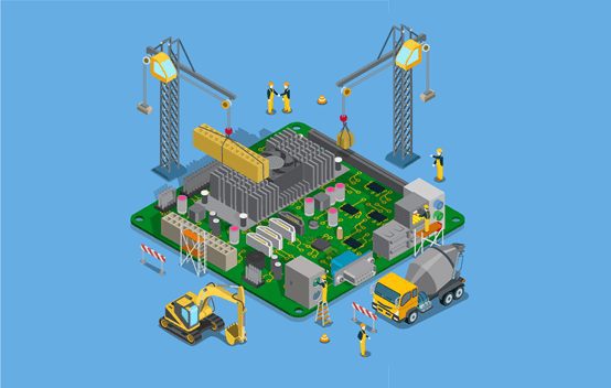
If you just stare at a corner, imagine the PCB as a chassis, the car, the engine, the sensors, the axle, the wheels, all form the electronic components on the circuit board.
Reliability is critical for automotive printed circuit boards. They need to survive in extreme environmental conditions and vibrations without any performance setbacks. In addition, the circuit board is expected to be fully operational in the long term. Heat resistance and service life make automotive printed circuit boards distinct from other printed circuit boards. PCB manufacturer must comply with ISO/TS 16949 standard, which is based on ISO 9001 automotive standard.
So, what are these special types of PCBS made of? What kind of substrate is used? Do they have enough heat sinks? So let’s see.
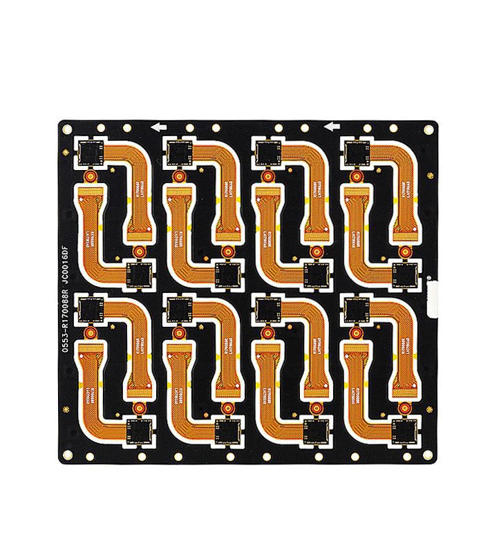
Flexible PCB – These plates are made of flexible plastic substrate. They are made of PEEK, polyamide, or transparent polyester film. These plates can be twisted and bent. Find their apps on car corners and corners.
Rigid PCB – Rigid plate made from FR4. These boards are not flexible. They are commonly used in display screens and reverse CAM screens.
Rigid flexible PCB – These boards are a combination of rigid and flexible PCB’s. They are implemented in lighting systems.
HDI PCBS – These boards have higher line density per unit area, thinner lines and Spaces, and higher pad connection density. HDI boards can accommodate more components and play an important role in miniaturization. These circuit boards are widely used in infotainment systems.
LED PCB – LED substrates are made from aluminum substrates as they require heat dissipation. They can be found in car indicators, headlights and brake lights.

Ceramic substrate PCB – Ceramic substrate is composed of high temperature co-fired alumina and aluminum nitride. These circuit boards are implemented in the engine compartment because they can withstand high temperature changes.
PTFE PCBs-Polytetrafluorin (PTFE) PCBs can withstand high frequencies and find their use in safety systems and/or radar technology. Metal core PCB – The metal core PCB consists of an aluminum base. The base layer is aluminum alloy plate, on which the whole plate is constructed. The base is used as a radiator and is therefore suitable for heat transfer applications. The metal core provides improved electrical insulation and thermal conductivity. These boards are used in anti-lock braking systems (ABS).
Heavy copper PCB – Automotive printed circuit boards use thicker copper (Cu) plates in the outer and inner layers. These heavy copper plates are more popular than ordinary ones because they can withstand high temperatures, high frequencies and high currents. Copper thickness of conventional circuit boards is about 25 m to 50 m. However, heavy copper PCB’s are 150 m to 200 m thick. These circuit boards are implemented in security and signaling systems.
As more and more chips are integrated together, the materials that hold them together will play an important role.
Automotive PCBS must meet stringent thermal cycling tests, thermal shock tests and temperature and humidity tests before consideration. Defects in the conductive anode filament (CAF) must be suppressed in the circuit board. CAF can cause a short circuit between the copper clad laminate (CCL) and the conductive trace line. The main focus is on self-driving cars, and the safety of truly driverless cars is questionable. However, when approaching the stationary vehicle quickly, the system with automatic braking has successfully started the braking. Cars increasingly rely on reliable printed circuit boards through microchips that control engine performance and vehicle safety. All safety features, such as drowsy driver alarms and blind spot detection, require PCBS.
The current development trend of automobile industry will increase the added value of automobile electronic products. For PCB, the technology will be able to handle multiple 100A high current and GHz amounts of information processing.
From the point of view of product performance, it far exceeds the function of PCB in the automobile, and new concept needs to be adopted. Most of the technologies associated with signal processing in PCB can be used in the consumer product industry, but when used in the automotive industry, the necessary quality and reliability requirements must be converted. For power electronic products, it is necessary to develop new PCBS in order to make them mass produced for a larger market. But so far, only small batches of power electronics have been produced.
PCB is a key component of these electronic systems. Considering the requirement of high speed, PCB is not just a connecting part between devices. Special attention must be paid to PCB failure modes that may cause short circuit or open circuit. In a driverless car powered by hundreds of volts, the PCB must be thoroughly understood to keep it running reliably. Common loads and major failure modes of PCBS during production and product life.
PCB environmental load: temperature cycling and storage, bending, vibration, humidity, a combination of several loads
PCBA environmental load: reflow welding, selective welding, pressing technology
Possible failure modes: copper-plated hole or inner copper layer crack, outer copper layer crack, microconductance hole crack, semi-cured piece crack, solder mask crack, electrochemical migration of PCB surface.
The specific requirements of a car for a PCB are influenced by its lifetime environmental load such as temperature, humidity, and vibration load. Depending on the specific application, diversification requirements will increase. On the one hand, electronics are getting smaller and closer to actuators (such as engines), such as power electronics, which can withstand higher temperatures. On the other hand, electronic devices such as on-board computers are better protected against external stresses, requiring longer service lives due to charging times and round-the-clock service.
Functional requirements are also varied. Using a PCB in an electric vehicle may be a cost-effective solution, but the PCB must be able to withstand a vehicle environment of several hundred amperes over a 1-million-hour life and up to 1000 volts.
To meet the signal processing requirements of autonomous and connected cars, the car’s HDI technology will have to take a big step forward to be able to use thousands of processors and memory with I/O and BGA intervals of less than 0.8 mm.High speed requirements require the use of new materials, which must respond to environmental requirements, especially humidity and temperature. High speed requirements require the use of new materials, which must respond to environmental requirements, especially humidity and temperature.
Failure modes caused by temperature and humidity in the environment
For automotive electronics, the industry has long focused on failures due to temperature cycling, and materials have been optimized for this failure mode. But humidity and temperature are also critical, although many applications of cars attest to self-heating in operating mode. Before starting, the car may be left in a humid environment for several days or weeks, and humidity may enter electronic products through plastic or atmospheric compensation kits.
The influence of humidity on PCB surface and internal structure is the main problem, and possible failure modes have been studied in detail. This article will therefore emphasize failures due to temperature, humidity, and bias (THB). Even if there is no condensation, high humidity can cause an electrical short circuit if materials are not carefully selected. Surface insulation resistance (SIR) will drop, which may cause electronic products to fail. Our method is to thoroughly understand the temperature and humidity conditions inside the protective enclosure (metal or plastic enclosure) through simulation and experimental testing. On the other hand, according to the SIR test method in IPC-9202, the materials (such as PCB, device, flux, heat dissipation interface material or cladding coating) and design elements will be identified under different temperature and humidity conditions.
Within the PCB, humidity is also critical, and different types of failure modes can occur due to electrochemical migration (ECM). Conductive anode wire (CAF) or hollow fiber is a known failure mode in the industry. It is necessary to study the cracks of PCB or bulk material in the deformation area and interface around the plating through hole. Resin cracking can be caused by temperature drop, high pressure, bending and/or mechanical loading. In addition, the properties of PCB materials under high pressure also need to be studied. All of this is necessary to ensure the insulation characteristics of the PCB.
In order to ensure the stability of PCB substrate in automobile electronic products, the local environmental conditions such as temperature and humidity in PCB in electronic system are simulated. The simulation conditions will be compared with the load capacity and design of the materials used. The life model is helpful to translate the PCB identification test results into the actual condition of the electronic system and to determine the appropriate distance of the design criteria in the PCB. At the same time, the CAF failure mode was simulated, and other cracks in the PCB were considered to be simulated.
At present, the identification test and life model are still under development.If no applicable life model is available, the material or failure mode must be removed by material limitations or strict process controls (e.g., for hollow fiber failure modes).
High speed requirements
For interconnectivity or image recognition (up to 10GHz in the future), high-speed applications such as radar (77GHz), and signal processing, the substrates and design rules elements need to be clearly defined. Impedance controllable PCB lamination and PCB supplier process control are standard in the consumer industry. The automotive industry must ensure high quality signal integrity, power integrity, and good electromagnetic compatibility. Special attention needs to be paid to the selection of materials to ensure their stability in temperature, humidity, and bias in addition to electrical properties, which will lead to restrictions on material selection and design rules in the future. To ensure necessary electrical performance, identify PCB suppliers for high speed applications. Considering the electrical characteristics of PCB substrate (Dk, Df), automobile application must consider the influence of production tolerance and environment, such as temperature and humidity will affect the electrical value. For example, the relative dielectric constant and dielectric loss of the material decrease during thermal aging, but the dielectric constant increases with the increase of water content in the epoxy resin material.

The functions and requirements of automotive electronics are facing dramatic changes. olutions for the consumer product industry can be modified or adapted to meet automotive product requirements, and new ideas for mass production of power electronics must be developed.
To sum up the higher requirements of automobiles:


XPCB Limited is a premium PCB & PCBA manufacturer based in China.
We specialize in multilayer flexible circuits, rigid-flex PCB, HDI PCB, and Rogers PCB.
Quick-turn PCB prototyping is our specialty. Demanding project is our advantage.
Tel : +86-136-3163-3671
Fax : +86-755-2301 2705
Email : [email protected]
© 2023 - XPCB Limited All Right Reserve
