- +86-755-23012705
- Building 3, Jinfeng Industrial Park, Fuyong Street, Baoan District, Shenzhen ,China
- [email protected]
Menu
Complex electronic equipment and (auxiliary) systems serve us in aircraft, trains, trucks, passenger vehicles, and important applications such as building infrastructure, manufacturing equipment, and medical systems. High reliability (the ability of a product to meet all the requirements of a customer’s environment within the expected life cycle) is becoming increasingly important. Big data and artificial intelligence are making humans more dependent on electronic systems and will make the lack of reliability even more deadly. Recently, at DesignCon 2020, I had the opportunity to learn how ANSYS allows engineers to design products with high reliability.

ANSYS, based near Pittsburgh, Pennsylvania, was founded in 1970 and now has about 4,000 experts in the fields of finite element analysis, computational fluid dynamics, electronics, semiconductors, embedded software, and design optimization. ANSYS is a well-known partner for very demanding customers in space and aircraft applications. Then ANSYS grew rapidly through the acquisition of other EDA suppliers. They acquired Ansoft Corp. in 2008 and Apache Design Solutions in 2011. Then in 2019, ANSYS acquired DfR Solutions, the industry’s only automated design reliability analysis software, Sherlock.
Combined with Sherlock’s precise reliability analysis, ANSYS’s integrated multi-physical field solution provides a complete designer suite that helps customers quickly and easily analyze electronic failures early in the design cycle, saving users time and money during development. Acquiring DfR electronic reliability solutions strengthens their capabilities for semiconductor packaging, PCBA simulation, and the ability to characterize and generate libraries and analyze and test various electronic components.
Analyzing the reliability of prototypes and/or pre-production units using a test failover approach is expensive and time-consuming, and results are not available until the end of the product life cycle.
ANSYS Sherlock Finite element Analysis (FEA) enables engineers to easily evaluate the reliability of hardware designs at the beginning of the design cycle. This also enables designers to weigh different architectures, geometries, and materials early and across a wide range of conditions to get the best results.
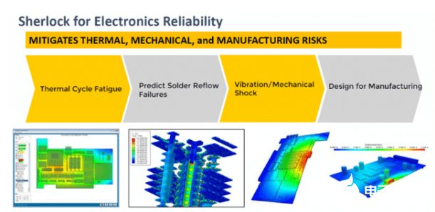
In a crowded conference room, Kelly Morgan, chief application engineer at ANSYS, presented three examples of failure mechanisms in which Sherlock could bring great value. Sherlock and ANSYS use physical failure principles to predict hardware reliability:
There is much more information than is provided below.
Dielectric materials with a low dielectric constant (K) reduce parasitic capacitance, improve circuit performance, and reduce power consumption. However, the lower mechanical strength of the thermo-mechanical force due to the difference in thermal expansion coefficient (CTE) can sometimes lead to cracks in the dielectric during refluxes or thermal cycles. The cracks can be found by acoustic examination. If the low k material is found to have cracks at the end of the product launch, a redesign cycle is required. By contrast, Sherlock and ANSYS allow IC designers to predict such failures at the start of a project and take corrective action immediately to prevent them.

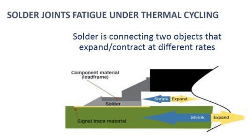
Many integrated circuits traditionally use lead-free solder bumps as connections to other cores, packages, and even printed circuit boards (PCBs). Different thermal expansion coefficient and temperature in adjacent layers will cause different expansion and contraction of the material. These thermomechanical forces, vibrations, mechanical shocks, etc., strain the solder joints and may cause cracks in the solder joints and interconnect surfaces. More recently, copper columns have become popular because of their smaller solder joint spacing. However, these interconnections are more rigid and may fail more quickly depending on the strain applied. The multi-physical features of Sherlock and ANSYS Mechanical allow users to easily and accurately predict the reliability of this interconnection, and to make changes to the driver early in the design cycle if needed.
With the smaller and smaller space in electronic devices, the application of micro-through hole technology in PCB has exploded. Micropores stacked up to three or four stories high have become very common. However, if these designs do not use the right materials and geometry, the micropores may experience unexpected cracking and layering.
Thermal-mechanical stress, moisture, vibration, and other stresses can lead to separation of micropores and layering of copper trace lines at the top or bottom of electroplated through holes (PTH). Sherlock analyzes these problem areas, taking into account overstress conditions during backflow and/or operation, and can predict when fatigue will lead to interconnect failures between through-holes, through-holes, routing layers, and UBM contacts under convex points.

Even a point-of-best tool like Sherlock needs to be integrated into a user-friendly, highly productive design flow to provide its full value in a customer’s design environment. By using upstream and downstream tools for smooth data exchange, engineers can quickly and efficiently exploit Sherlock’s many capabilities. This design flow integration minimizes scripting, data format conversion, and error-prone and time-consuming manual intervention. Sherlock interacts with ANSYS’s Icepak and ANSYS Mechanical to combine these tools into a highly productive and very reliable design process to achieve the “zero defect” goal required by increasing applications.
Ansys Icepak provides powerful electronic cooling solutions for a thermal and fluid flow analysis of integrated circuits (IC), packages, printed circuit boards (PCB), and electronic components using the industry-leading Ansys Fluent Computational Fluid Dynamics (CFD) solver. The Ansys Icepak CFD solver USES the Ansys Electronics Desktop (AEDT) graphical user interface (GUI).
This provides engineers with a CAD centric solution that enables them to manage thermal problems within the same unified framework as Ansys HFSS, Ansys Maxwell, and Ansys Q3D Extractor, using an easy-to-use functional area interface. Electrical and mechanical engineers working in this environment enjoy a fully automated design process that enables seamless coupling of HFSS, Maxwell, and Q3D Extractor to Icepak for steady or transient thermal analysis.
Engineers can rely on Icepak to provide integrated electronic cooling solutions for a variety of electronic applications, from single Ics to packages and PCBs to computer casings and entire data centers. The Icepak solver performs conduction, convection, and radiation conjugate heat transfer analysis. It has many advanced features to simulate laminar and turbulent flow as well as multiple types of analysis, including radiation and convection. Icepak provides a huge library of fans, radiators, and materials that provide solutions to everyday electronic cooling problems.
5G connectivity is the coming technology revolution. This ubiquitous, ultra-fast computing network will connect billions of data-driven devices. This will drive economic expansion across industries, create new products and services, and change the way we live as we know it. However, before 5G can fully fulfill its promise and meet its quality-of-service (QoS) targets, wireless system designers and engineers will have to overcome quite a few challenges. The Ansys 5G simulation solution allows those involved to simplify the complexity of the device, network, and data center design.
The Ansys 5G Simulation solution provides electromagnetic, semiconductor, and electronic cooling and structural analysis tools to accurately simulate 5G radio and related technologies. The multi-solution platform leverages high-performance computing that can be deployed across the enterprise, enabling more efficient collaboration between designers and engineering experts.
The design process of phased-array in ANSYS HFSS. ANSYS HFSS is a 3D high-frequency electromagnetic (EM) tool that can be used to design and simulate numerous HF electronic products, such as antennas, antenna arrays, RF and microwave components, resonators, filters, and other HF electronic components. The phased array design process in HFSS starts from a single unit prototype, and the antenna design parameters are optimized by the experimental design (DoE) method. The entire array is then synthesized by the unit for simulation optimization of the entire array performance in ANSYS HFSS, followed by modeling and simulation of the installed antenna and its interaction with the environment using a hybrid ANSYS HFSS SBR+ ray-tracing solver.


XPCB Limited is a premium PCB & PCBA manufacturer based in China.
We specialize in multilayer flexible circuits, rigid-flex PCB, HDI PCB, and Rogers PCB.
Quick-turn PCB prototyping is our specialty. Demanding project is our advantage.
Tel : +86-136-3163-3671
Fax : +86-755-2301 2705
Email : [email protected]
© 2023 - XPCB Limited All Right Reserve
